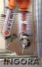
Arc Welding
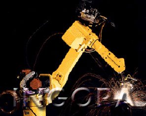 Arc welding is technique by which workpieces are joined with an airtight seal between their surfaces. The principle of the process is the fusion of two metal surfaces by heat generated from an electric arc. During the welding process, there is an ongoing electric discharge -thus the sparks between the welding electrode & the workpiece. The resulting high temperatures of over 330 C melt the metal in the vicinity of the arc. The molten material from the electrode is added to supplement the welding seam. Whereas spot welding is performed with alternating current, arc welding is performed with direct current, usually 100-200 A at 10-30 V.
Originally arc welding used carbon rods for electrodes. However, they didn’t add material to the weld, so metal filler rods had to be added. Modern methods essentially have replaced the carbon arc welding by providing quality solutions to the welding requirements. Some of these methods are: TIG, MIG, GMAW, GTAW, SAW, & FCAW. In some methods to prevent oxidation of the molten metal, electrodes are coated with flux material that melts during the welding process. Inert gas such as helium or argon serves also to prevent oxidation. Automatic, electric arc welding equipment is comprised of a line through which continuous electrode wire is fed. The wire forms a tip that is graded along the desired weld trajectory. The application of laser-based vision systems to welding processes results in quality assurance improvements, technical feasibility, increased welding speed, savings on consumable materials, & a solution to the shortage of trained workforce. The objective of the sensing system is to provide information for motion control. Torch position & orientation & welding parameters such as arc current, arc voltage, arc length & torch weaving. Laser-based vision systems provide also the capability of performing 100% inspection.
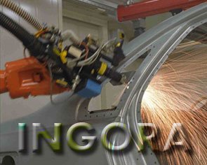
Spot Welding
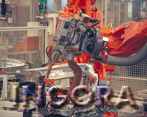 One of the main applications of robots has been & still is in spot welding. This proliferation is not due to its process simplicity; On the contrary, it’s a complex one! However, it’s a good example of cost-justified application that also, relieves humans from a tedious & difficult job. Furthermore, the automotive industry around the world joined forces with robot makers to improve & advance this application area.
Spot welding robots often work three shifts (with the third devoted partly to overall line maintenance), & produce sometimes well over 150 cars per hour. All major car manufacturers use robots for spot welding because of their speed, accuracy, & reliability. The repeatability & consistent positional accuracy that spot welding robot can achieve provide for much better quality product than in manual operation. In some cases this can be done with fewer spots welded in locations that can be accurately & precisely controlled.
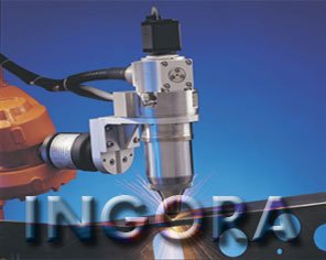
Laser Welding
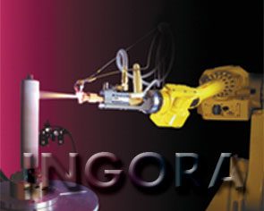
 Laser welding is the most promising of the advances in non-contact welding. However, its application has been slow to take off for robotics-based welding processes. Bulkiness of laser beam generation devices & difficulties with the beam driving along the robot’s arm are among the barriers preventing the widespread implementation of robotic laser welding systems in industry. Recent advances in yttrium aluminum garnet (YAG) laser & fiber optics for laser beam conduction are bringing industrial implementation of laser welding systems closer to reality.
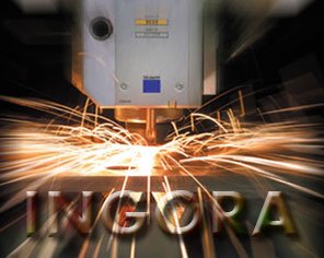
High-power CO2 laser welding has been widely used in the industry as an alternative to both spot & arc welding due to its high productivity & excellent weld quality. Laser, highly coherent beam of light, can be focused to a very small spot, giving rise to high power densities of over 106 W/cm2. At these high power densities the substrate material evaporates because the beam delivers energy so rapidly that the mechanisms of conduction, convection, & radiation have no time to remove it. This leads to the formation of a keyhole. The keyhole can be considered as a cylindrical cavity filled with ionized metallic gas, which absorbs 95% of the power. The equilibrium temperatures reached are about 25,000 C. A curious phenomenon is that the heating occurs from the inside of the keyhole outward, not from the surface of the material down (as in conventional welding processes). This causes a pool of molten metal to form all around the keyhole, which hardens behind to it to form a weld as the beam moves along. Typical speed of the beam can reach several meters per minute! The keyhole mechanism provides high aspect ratio (depth-to-width) welds in steel, where 10:1 ratio is common.
Plasma Welding
 Plasma welding is the ideal welding process for welding plates in thicknesses of up to 8 mm. In the range of 0.1 to 2 mm, plasma welding is very reminiscent of TIG welding, but it has a more concentrated & defined arc column.
In the range of 3 mm & upwards, the key-hole welding technique offers a number of advantages such as high welding speed, low heat input, small deformation & high quality & finish of the weld.
Projection Welding
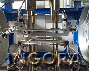 Resistance projection welding is a process in which the welding heat is localized at a predetermined point established by the design of the part. Electrical current flow is concentrated in one or more projections in one of the parts, & heat is generated, Normally, the projection heats to a plastic temperature at which point it collapses due to the electrode force at approximately 20 to 30 percent of the total weld time. Heat continues to be generated in both parts until sufficient nugget growth is realized & then the current is terminated.Projection welding is a rather tolerant process, permitting parameter variations to occur without seriously affecting the integrity of the weld. How-ever, for light materials, the process becomes more critical, As projections collapse under the initial die impact of force, heat is dissipated into the tooling instead of in the projection & it is exaggerated even more by the heating & cooling of the sinusoidal current in AC power. For coated materials this has presented additional problems with coating material pick-up on dies, the surface coating being burned away, & higher currents being required.One approach to resistance welding that’s well established for steel is now being perfected for aluminum. Projection welding is already widely used for joining steel in the automotive, appliance, & other industries. The core applications for projection welding method are automotive closure panels & thin 0.020 to 0.060″ (0.5 to 1.5 mm) materials.Projection welding uses a stamped indentation on one of the welded sheets to concentrate electrical energy through a small metal-to-metal contact area. This results in an efficient weld, created from just one side of the sheet in only 4-6 milliseconds. “The benefits of the process are low heat input & minimal marking. When the process is applied to automotive outer-panel hem joints, the weld is invisible on the show surface. Distortion on the show surface is less than 9% of total paint thickness typically used on closure panels, both steel & aluminum.Key to projection welding’s success is the embossed projection’s geometry. Cylindrical, conical, & ring embossments are common for steel welding, but these shapes haven’t worked well for aluminum with its higher electrical conductivity & lower strength. So the researchers have come up with a new projection geometry for aluminum to properly manage weld-current density to allow consistent welds.Admittedly, producing any kind of projection embossment does require extra tooling for inner closure panels. Steel panels can have projections produced in the stamping die or in a separate station just before the marriage station, which places the inner panel on the outer, just prior to the hemming station. Aluminum panels require the separate station for projection forming.In most cases customers have chosen the cheapest route, which is to form projections in the stamping die. But it was very difficult to get die makers to produce the projection the process requires. Thus, INGORA encourages the use of specifically designed projection-forming equipment & the company insists this be used for all aluminum panels welding.
Laser Cutting
 Metal cutting lasers continue to evolve at an amazing rate, largely based on the demands of OEMs & job shops, while profit margins shrink because of increased competition & lower pay rates. To help fabricators meet the demands placed on them, laser manufacturers are creating new laser features that help fabricators differentiate themselves, speed up productivity, & get more out oftheir laser machines.
40 years ago no one would have thought it possible to cut plate steel with focused light. Over time it has not only become possible but common in manufacturing operations. However, making this science fiction into fact wasn’t enough, & industrial lasers continue to evolve at an amazing rate.
One of the challenges for robotic laser cutting is ensuring that a cut slug has actually dropped out of a part. Formerly this was accomplished using mechanical check gauges or visual inspections, which are labor-intensive methods that sometimes produced inconsistent results. If inspection determined a slug was still present, the part either had to be sent back through the entire process or through a repair process.
We now laser-cut feature-to-feature—in cycle—using sensors to determine if the slug has fallen out of the cut feature. If the slug doesn’t fall out, the robot senses it & takes immediate corrective action within the laser cutting process cycle. This ensures that a part won’t cycle out of the cell until it is completely cut—or the operator is alerted to the fact that a defect exists & corrective action might be required.
Another key development in robotic laser technology involves automatic alignment of the laser. Laser focus is critical in processing parts effectively. INGORA continues to investigate sensors & techniques for automatically aligning the laser focus & automatically compensating the robot path for any deviations.
Compressed air, or shop air, can be used as an inexpensive assist gas for laser cutting of thin-gauge material up to 0.080 in. It can be used to cut steel, stainless steel, galvanized steel, aluminum, & titanium. With 80 percent nitrogen & 20 percent oxygen, air-assisted cutting does not suffer from the same cut-speed-limiting thermal effects as pure oxygen-assisted cutting. Air-assisted cutting offers greater feed rates than that of nitrogen cutting. Accordingly, the edge finish resulting from air-assisted cutting is not as clean as a nitrogen cut but has much less oxidation than an oxygen-cut edge.
Plasma Cutting
 Plasma cutting is a process that uses a high velocity jet of ionized gas that is delivered from a constricting orifice. The high velocity ionized gas, that is, the plasma, conducts electricity from the torch of the plasma cutter to the work piece. The plasma heats the work piece, melting the material. The high velocity stream of ionized gas mechanically blows the molten metal away, severing the material.
Plasma cutting is ideal for cutting steel & non-ferrous material less than 1 inch thick. Plasma cutting is also easier for the novice to master. Another benefit of plasma cutting is that when it comes to thinner materials it is much faster at cutting than oxyfuel. Plasma cutting can be performed on any type of conductive metal. Operators will find that when plasma cutting mild steel their job will go a great deal faster & have thicker cuts to show for it.
We can outfit a multiple number of robots from our inventory for any plasma cutting job. If you are confused about which robot will benefit your company the best when it comes to plasma cutting then please feel free to call us & one of our applications staff will be happy to answer any & all of your questions.
Laser plasma cutting is a new process that offers faster cut speeds—up to approximately 250 percent faster. In laser plasma cutting, gases escaping from the melt pool are ignited to form a blue plasma cloud. This plasma cloud directs additional energy into the cut kerfs, resulting in higher cutting speeds.
Alternative Materials: an emphasis also is being placed on cutting materials other than mild steel. Aluminum & stainless steel both are being cut on laser systems more commonly, & this trend will intensify in the future.
Most laser systems can cut alternative materials. But, now the industry is starting to focus more on these alternative metals.
Previous machines have been designed to offer reasonable cutting results in various materials rather than optimal results in one material. But, new technological advancements, such as the programmable beam diameter, allow optimal cutting results for each material.
Water-jet Cutting
 Water jet Cutting is a process that offers cost effective manufacturing solutions across a broad spectrum of applications. Just about any material up to 150mm thick (and in some cases thicker) can be cut to produce precision components, large or small in simple or the most complex of shapes.Because Water jet cutting is a cold process, the molecular structure of the material being cut will not change & together with the fact that there are no cutting forces, components are produced free from Stress & Distortion. The edge finish is clean & of high quality as well as being free from burr.
Grinding
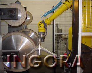
 Grinding robots remove excess material from the surface of machined products quickly & efficiently.
Manually grinding welds is tough, dirty & noisy work, & the metal dust produced by grinding is harmful to workers’ eyes & lungs. Grinding that once took 96 man-hours per shift manually now takes a robot less than 10 hours. Robotic grinding also produces more consistent, high-quality results.
Since the global economy is placing new demands on manufacturers both from the standpoint of competition & more stringent operating requirements now more than ever is a good time to purchase a robot for grinding automation.
It is the ability of the robot to determine the shape, size, weight, or even the surface texture of an object by touching it. The contact sensors are situated in the design of the gripper of the robot to provide the robot with information about the forces in the wrist or the joint of the robot & also in the objects that are to be handled. It is very important for robots to determine this information especially in fettling & grinding operations & in assembly operations.
Inventory of grinding robots is quite extensive & we are sure we will be able to find you the right robot for your job.
Finishing
 The same industry forces of nature—globalization, economic conditions, quality demands, & safety & environmental regulations—that are pressuring metal fabricators to do more, better, & faster with less are blowing no less forcefully on finishing fabricators. As cutting, welding, & other fabrication processes evolve & new materials emerge to meet these requirements, finishing processes have had to become a nimble dance partner to the whirlwind of change or get caught up in it.
New developments in fabricating technologies have new plate finishing consequences:
• Laser technology advancements make them able to cut thicker metals but create different finishing needs;
• Faster cutting methods sometimes produce lower edge quality;
• Plasma cutting is powerful enough to cut plate as thick as 5 inches, but the thicker the plate, the greater the dross & slag;
• Cutting faster with some types of water jet machines & other machinery creates jagged edges & irregular geometries;
• Robotic welding saves time but requires a different kind of edge treatment;
• The growing use of precoated & clad materials poses finishing challenges;
• Fabricators are pushing for more flexibility from their equipment;
• Automation is both the result of forces driving changes & a catalyst for change;
• & perhaps most consequential for the finishing industry, fabrication processes are being developed that attempt to eliminate the need for finishing as a secondary process altogether;
Deburring
 A major motorcycle manufacturer utilizes a product to allow a previously slow & repetitive manual process to be automated. Cooling fins on a cylinder head are deburred using a high-speed die grinder mounted to a force compliance tool. This system enabled the manufacturer to increase throughput & quality on a sensitive engine component.
Spray Painting
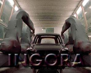 Industrial robots utilized in spray-painting applications are not quite similar in appearance & functions to robots in other application fields, because of the environmental conditions in spray-painting. Spray-painting robots in themselves should not be viewed as the complete solution to all painting problems. Rather, they should be recognized as integral parts of an automated system. Like the other forms of automation, spray-painting robots should possess the capability to complete their tasks & complement the total production operation. Today’s spray-painting robots can consistently duplicate the best work performed by skilled human painters, provided that sufficient time is allowed to adjust & refine the programming. Once, the robot is programmed, it will repeat the exact motion of the sprayer/programmer & provide quality results, whether the application is final top coat, primer, sealer, mold release, or almost any other material deposition.
The controller of the robot also, provides the capability of interfacing with other equipment supportive of the spray-painting system, including color changers, conveyors, life & transfer tables, & host computers. In fact, using the robot’s controller capabilities can alleviate many of the design & operating concerns associated with present-day production spray-painting systems.
Today in the painting, industrial robots are applying automotive exterior top coat & under-body primer, stains on wood furniture, sound deadeners on appliances, porcelain coating on kitchen & bathroom fixtures & appliances, enamel on lighting fixtures, & even the exterior coating on the booster rockets that propelled the space shuttle into orbit.
Spray Coating
 An attempt to reduce cost & improve quality for customers, a major supplier of refractory materials can turn a system to automatically reline continuous casting tundishes.
This system utilizes a robotic arm on the end of a PLC controlled traveling gantry to automatically spray refractory material inside continuous casting tundishes. This 6-axis robotic system was designed to replace the slow, dirty, unsafe, & non-uniform hand application of refractory material.
The project contains entire system from concept development through layout & design. This included the material handling systems, mixing station, variable speed pumping system, the interface between the robotic arm & gantry, programming of the arm & gantry, procurement & installation of the system, construction management, de-bugging & start-up at the client’s facility.
Sealing/Dispensing
 Industrial robots are increasingly utilized for material dispensing, especially in application of sealants & adhesives. The following major factors motivate this application area:
• Applying just the right amount of adhesive, sealant, or other materials;
• Consistent & uniform material dispensing;
• Process flexibility;
• Improved safety;
The major application of sealing & adhesive dispensing are in the automotive, appliance, aerospace, & furniture industries. Any process that requires joining of component parts in a variety of production is a potential candidate for robotic dispensing. In the area of adhesive application, one can certainly say that adhesive bonding is as important to the assembly of plastic parts as welding has always been to metal joining.
The automatic sealing of refrigerator cases using foamed hot-melt adhesive & a robot has demonstrated a process of potential benefit to many industries today. Sealant applications are plentiful & possibly limited only by the adhesive chemistry & robot characteristics. For example, robots can be used to seal body panels in the automotive industry or provide a means for in-place gasketing in the appliance, automotive, or other industries.
Gluing/Glazing
 Robotic bonding is typically selected because of their fast-curing nature & two-component materials requirements. Mix & dispense systems should provide adhesive dispensing machines with robot held guns (nozzles), as well as fully automated dispensing machines that are integrated with production lines & robots. The key success factors for applying reactive two-component adhesives are: knowing the chemistry, accurately metering the individual components & finally mixing the two components as they are applied to a part. Available Systems, range in size from the Posidot for minute quantities of adhesive up to very large-scale meter-mix machines custom-built for robotic processes.
Flaming
 During the process in which car bumpers are produced, some metallic parts are inserted into the bumper body. To gain this propose, it’s needed to heat the region of insertion.
A robot equipped with oxy-fuel flaming system is able to heat the exact positions on bumpers. Adding the metallic parts may be automated too. So, another robot performs the action.
Die Cleaning+Resin Molding+Sand Blasting+Forging+Forming+Dipping
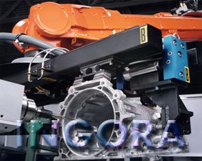
 The first recorded application of robotics in die casting dates back to 1961 in Ford Motor Co. The anticipated benefits of this initial application -namely, improved worker safety & more predictable production output- were soon realized. In addition, part quality also improved, thanks to the regularity of the robot operation, which maintained die temperatures at a constant level to improve the consistency of the castings.Robots are the solution to a wide range of other problems in the die casting foundry as well. They perform both pre- & post-process operations with a precision & regularity not possible with even the most skilled operators -in one of the most hazardous of industrial environments, now often considered unfit for human occupancy. In fact, the real potential of robots in die casting didn’t begin to be realized until they were programmed to tackle some of the peripheral activities previously performed by human operators. Some tasks which can be performed by robots in this field are: Parts Integrity Checking, Cooling, Trimming, & Storage, pouring Metal, Die Insertion, Die Lubrication, & so on.In Aluminum Casting, articulated robots are used in the same application areas as they are in general die casting facilities.One of the most notable developments has been the use of robots in the manufacturing of sand cores. The industrial robots have the strength, precision, & dexterity to handle the relatively delicate but often very heavy sand cores. Other sand casting tasks performed by robots are part insertion, core deburring, & gluing of multiple component cores. Robots are also, being successfully installed for cleaning in sand core foundries.